
Interpreting the components of protocols that use torsional analysis in VisualEyes™
Description
It is relatively simple to track horizontal and vertical eye movements using videonystagmography (VNG) because they can be directly deduced from the position of the pupil. However, torsional movements, which are rotational movements around the line of sight, can be challenging to measure because they cannot be directly deduced from the pupil position.
This is because the pupil is normally round and thus rotationally invariant. Adding physical markers to the eyes to measure torsional movements is possible but invasive. Alternatively, in VisualEyes™, we adapted an algorithm from Johns Hopkins University School of Medicine that can quantify torsion by tracking the movement of visual structures in the iris.
Two of the protocols in VisualEyes™ can measure and quantify torsional eye movements. An automated calibration procedure is included in the software, so these protocols are simple to use. Below are descriptions of each, including how to read and interpret the torsional data.
Related course: Advances in VNG
Understanding torsion in the Ocular Counter Roll (OCR) test
The Ocular Counter Roll (OCR) test is a clinical test to assess otolith function, which requires the torsional eye tracking algorithm. In the OCR test, the eyes will roll in the opposite direction of the head tilt. When the head is tilting to the left, the eyes roll to the right and when the head is tilting to the right, the eyes roll to the left.
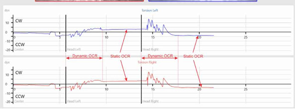
There are two components of the response: static and dynamic. The static component of the OCR is driven by the utricle and represents the change in eye position when the head is in the stable target position. The dynamic component occurs during the actual head roll movement and is a short burst of torsional nystagmus with the eyes beating in the direction of the head tilt.
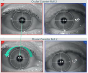
For example, when the head tilts to the left, the dynamic response will be a quick burst of left‑beating torsional nystagmus. These beats will look as if they are moving in the clockwise (CW) direction with respect to the clinician’s view (see Figure 1). The dynamic component is driven by both the utricles and the semicircular canals.
For the clinical assessment of the OCR test, we are only interested in analyzing the static component triggered from the utricle. This component occurs following the dynamic burst of nystagmus and is recorded and analyzed during the time the head is kept still at the proper tilt angle.
In Figure 1, you can see that the static component is to the right, which is counterclockwise (CCW) in response to the left head roll. You can also see a shift in the vertical plane; the left eye moves up and the right eye moves down.
Although we are referencing the head tilting to the right or to the left in the software using the 3D head model, it is actually the head and trunk that should tilt 30 degrees while seated in a chair. This standard procedure was established by Johns Hopkins University School of Medicine [1] to eliminate any contributions from the neck and ensure optimal responses.
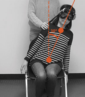
The patient above is tilting to the left and below is an example of what the eyes are doing during this movement. The head and trunk are rotated 30 degrees to the left and there is a counterclockwise (CCW) rotation of the eyes towards the right shoulder.
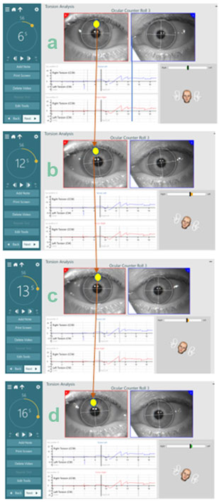
The pictures below show another example of the eye and head movement throughout the OCR test. Watch the time on the countdown clock and follow the eye and head movements through the short dynamic phase. The head model in each image shows the patient’s position throughout the test.
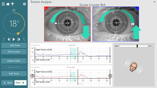
Understanding torsion labels
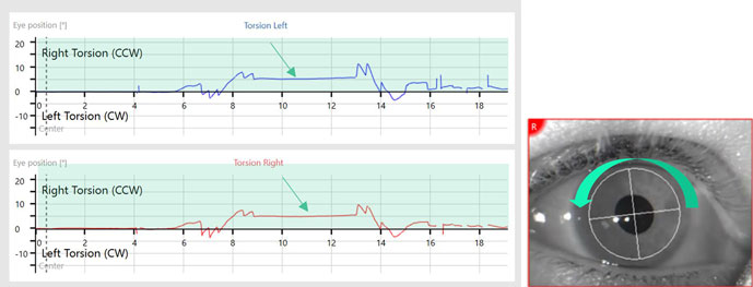
Below we see the eye position graph labels for a head movement to the left in the VisualEyes™ software, version 3.1. The label first reads Right Torsion. The ocular counter roll (right) is opposite the head movement (left). It also reads CCW (counterclockwise). This is CCW for the final eye counter roll position (which is the static portion of the response).
Static OCR gives us insight on the function of the utricle; therefore, we are most interested in this static portion of the response. The dynamic portion results in fast phases to the left which are CW (clockwise) in this example.
It should be noted that the labels of CW/CCW are from the clinician’s view and represent the final static eye position as indicated by the arrow in Figure 5.
In VisualEyes™ 3.0, the CW/CCW was from the patient’s view (so a left head roll resulted in CW to the patient’s torsion) but this has changed to make it consistent with the interpretation of the Advanced Dix-Hallpike test.
The “new” label in 3.1 utilizes CW and CCW to represent the static component of the response from the persepctive of the clinician. We adopted this terminology as it is consistent with the collaboration of Dr. Susan Whitney and Dr. Kamran Barin.
Understanding torsion in the Advanced Dix‑Hallpike
The Dix-Hallpike test is used to diagnose Benign Paroxysmal Positional Vertigo (BPPV) of the vertical canals. To confirm BPPV, there has to be a torsional eye movement present. Therefore, analyzing and quantifying torsional eye movements is critical in Dix-Hallpike testing.
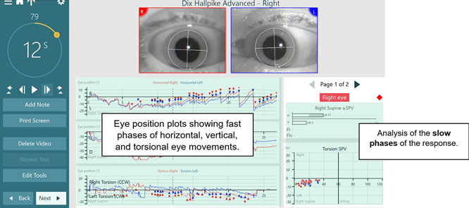
In VisualEyes™ VORTEQ Assessments, the “Advanced Dix-Hallpike” test allows for torsional analysis. Below are examples of the left and right Dix-Hallpikes, which include not only horizontal and vertical nystagmus tracings, but also torsional nystagmus tracings.
In addition to the bar graphs that plot the horizontal and vertical slow phase velocity (SPV) values, there is also a graph of the torsion velocity which plots the SPV of the eye movements.
Left Dix-Hallpike
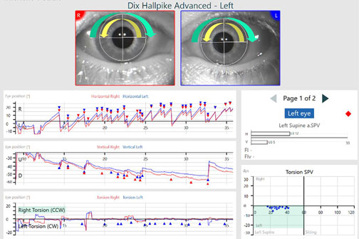
In this example, the patient has posterior canal BPPV. The patient is in a Dix-Hallpike maneuver, where their left ear is undermost as the patient is lying supine with their head off the table to the left. This patient has a left-beating horizontal nystagmus and up-beating vertical nystagmus.
The torsion eye position plot shows fast phases to the right which are labeled right torsion CCW and slow phases to the left which are labeled left torsion CW. This can be seen with the arrows on the eyes in Figure 7.
The yellow arrow represents the fast phase direction, and the green arrow represents the slow phase direction. On the righthand side, you see the Torsion Velocity plot where SPV of the left slow phases of the eye movements are plotted.
In the next example, you can see a patient with bilateral BPPV. Figure 8 shows the anterior canal involvement with the left ear undermost. The eye position graphs are showing the components of the nystagmus.
The first eye position graph is the horizontal eye movements, which are left beating. The second eye position graph is the vertical eye movements, which are up beating. The third eye position graph is the torsional eye movements that show the fast phases to the left, which are left torsion (clockwise). The slow phases are to the right (counterclockwise).
Right Dix-Hallpike
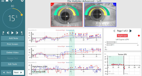
This example is the same bilateral BPPV patient now in the Advanced Dix-Hallpike right position, with the right ear is undermost. Figure 9 shows the right posterior canal involvement.
The first eye position graph is the horizontal eye movements, which are left beating. The second eye position graph is the vertical eye movements, which are up beating. The third eye position graph is the torsional eye movements that show fast phases to the right, which is right torsion (counterclockwise) and slow phases to the left, which is left torsion (clockwise).
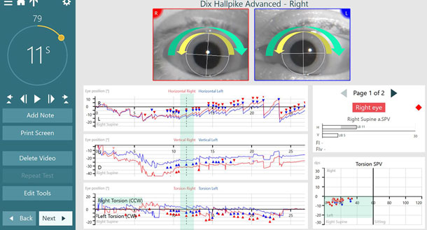
In summary, all eye movements (horizontal, vertical, and torsional) are referred to and plotted in the eye position graphs by their fast phases (see Figure 10). The bottom right graph shows the SPV of the torsional eye movements, where the dots represent the slow phases of the eye movements. Even though we call the eye movements by their fast phases (e.g., up beating, left beating), we always analyze the slow phases which are on the right side of the graph.
Conclusion
Previously in VNG testing, we have relied solely on the measurement of horizontal and vertical eye movements. However, our eyes do not only move in these two planes. And specifically in vestibular disorders, such as BPPV, the identification and analysis of torsional eye movements is critical for a successful diagnosis.
Torsional eye movements are reported based on the direction of the fast component of the movement of the eyes from the clinician’s perspective (clockwise or counterclockwise), but the quantitative values are reported on the torsion slow phases.
VisualEyes™ 3.1 has improved the torsion algorithms and the labeling of the graphs and data plots to make it easier to understand exactly how the eyes are moving in response to the head movements. These new features provide the means to make a more accurate clinical diagnosis.
References
[1] Sadeghpour S, Fornasari F, Otero-Millan J, Carey JP, Zee DS, Kheradmand A. Evaluation of the Video Ocular Counter-Roll (vOCR) as a New Clinical Test of Otolith Function in Peripheral Vestibulopathy. JAMA Otolaryngol Head Neck Surg. 2021;147(6):518–525.
About the authors
Michelle Petrak, Ph.D., is the Director of Clinical Audiology and Vestibular Research for Interacoustics. She is located in Chicago where she is a licensed private practice clinical audiologist at Northwest Speech and Hearing (NWSPH). Dr. Petrak received her doctorates in Electrophysiology (1992) and Biomolecular Electronics (1994) from Wayne State University and her Masters in Audiology in 1989.
Liz Fuemmeler, Au.D., is a Clinical Product Manager at Interacoustics. She graduated from Purdue University in 2019, and spent three years at Hearing and Balance Specialists of Kansas City as a Vestibular and Concussion Audiologist before joining Interacoustics in July 2022.