
How to perform the Advanced Dix-Hallpike test
The Advanced Dix Hallpike test is part of the VORTEQ Assessments bundle. The Dix Hallpike test is performed to look for Benign Paroxysmal Position Vertigo (BPPV) in the vertical canals. The Advanced Dix Hallpike test has 2 additional features that provide significant improvements over the standard Dix Hallpike test. The new features are:
- 3D Head Model Guide to show the head position of the patient in real-time and during playback.
- Guide to assist in proper head placement with exact degree of head positioning.
- Torsion eye graph with torsional nystagmus analysis.
- Pause during supine and seated positions to ensure clean data collection and reduce body movement artifacts.
- Automatic test start (optional).
Calibration
To perform the test, you must first calibrate the eyes in the software. This allows the algorithm to identify the iris and determine how far the eyes are from the cameras and how far they need to move to look at a target of known position.
First, select the Advanced Dix Hallpike Protocol from your existing protocols drop down menu.

Figure 1 – Test Menu
Make sure the VORTEQ sensor is turned on. Then select the calibration option.

Figure 2 – Calibration selection
Once in the calibration menu, you can perform 2 tasks:
- Calibrate the torsion eye tracker
- Calibrate the eyes to the visual targets
First, calibrate the torsional eye tracker. Have the patient fixate on a target in front of them. Then put the cover on the goggle so the patient’s eyes can dilate in the dark. As them to continue to look straight ahead. Torsion calibration should be performed with the cover on if Dix Hallpike will be performed with cover on.
![]()
Figure 3 – Torsional tracker calibration
Use the Auto Detect button to identify the appropriate iris tracking area. If the white tracking circles are not encompassing enough of the iris you can use the manual slider adjust bars to make small adjustments. When you are satisfied that the tracker is stable around the eyes then use the “Set Reference” button to finish the calibration.
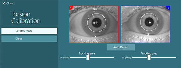
Figure 4 – Set Reference to complete torsion calibration
Next, calibrate the eyes to the TV monitor. Instruct the patient to hold their head still and look at each of the 5 targets.

Figure 5 – Video eye calibration
Performing the test
Once the system is calibrated, you are ready to begin testing. During testing, remind the patient to keep their eyes as wide open as possible. It is important to have good visibility of the iris. You will use the 3D Head Model to guide you through the appropriate head/body positions for the Dix Hallpike test.
- Step 1 is to turn the patient’s head 45 degrees towards the side you will be testing.
- Step 2 is to lay the patient down with the head hanging 10 degrees.
The black bar represents the head movement and when the head is in the correct position, the shaded area will turn green. Once you have reached the first position, you can immediately begin the second position.
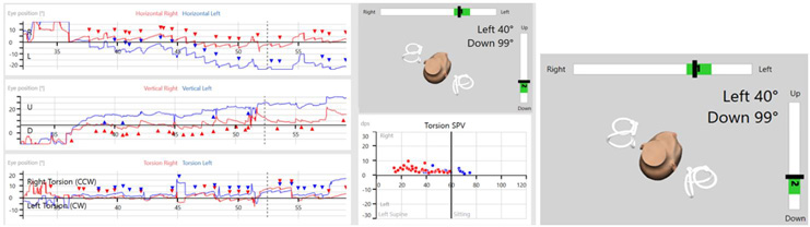
Figure 6 – 3D head model guide with exact degree positioning
Once the patient is in the correct position with both step 1 and step 2 highlighted in green, you can begin the data recording by pressing the start button or start on the remote control.
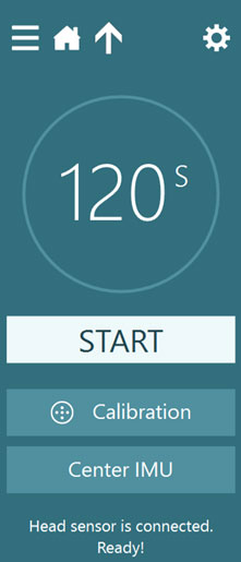
Figure 7 – Start the test
The eye recording will begin once you hit start. Recording will continue to run for the preset time or until you hit continue. Data recording will pause until you hit “resume”. This gives you time to get the patient into a seated position, while avoiding the addition of noisy data to the recording.
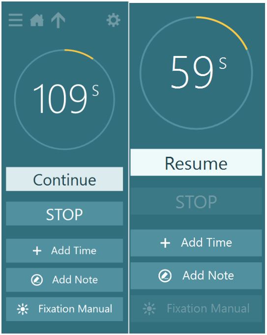
Figure 8 – Test sequence, when you’re ready for the seated position - press continue. The data will stop recording until you move the patient into the seated position and press ”resume”.
You should record at least 10 seconds of eye movements after the patient returns to sitting position to see if any nystagmus that was present in the supine position reverses direction when you sit the patient upright.
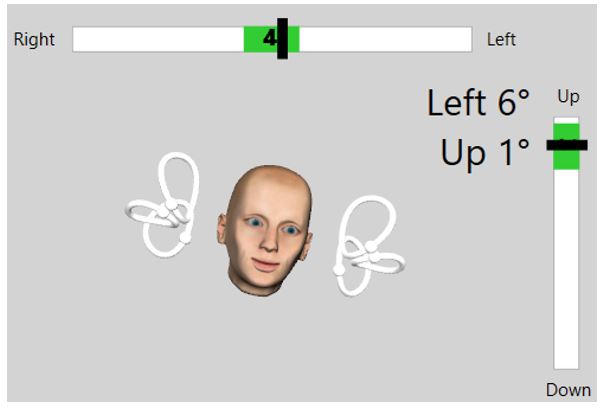
Figure 9 – The second section of the test requires the patient to be seated. The target angle bars will change to prompt a position change.
Results
After the test is completed, you will see the data graphed for the horizontal and vertical eye movements and the torsional eye movements. A red diamond will appear if BPPV is detected.

Figure 10 – Advanced Dix-Hallpike results screen
In the eye position plots for Torsion, eye movements greater than zero are plotted as right slow torsion eye movements, which are counterclockwise (CCW) to the examiner. Eye movements less than zero are plotted as left slow torsion which is clockwise (CW) to the examiner. In the Torsion SPV plot, the velocity of the slow phases of the torsion eye movements are plotted in degrees per second (dps).
Optional Feature – Automatic Test Start
Automatic test start is an option feature you can enable for a time-saving aspect of your protocol and appointment. To turn on this NEW feature, go to Protocol Management, VORTEQ Assessments, and click on Lateral Head Roll. You will see the “Automatic Test Start”. Click in the box so the checkmark appears. This means that the test will automatically begin a couple seconds after the patient is in the correct positioning (as represented by the head model and green target bar).
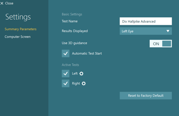
Figure 11 – Automatic Test Start
For further assistance, if needed, please refer to the Instructions for use and Additional Information manuals.
Presenter
