
How to use VisualEyes™ EyeSeeCam
Standalone ESC vHIT includes a Spontaneous Nystagmus test where you can record eye movements before beginning your vHIT test protocols.

Figure 1 - EyeSeeCam standalone default protocol
If you purchase licenses for both ESC vHIT and VNG, you can opt to use the ESC goggle for some of the VNG protocols.
Performing tests with ESC Goggle
You should always start by calibrating the system. For the lateral canals, you will calibrate the eyes to fixed targets.

Figure 2 - Calibration prompt before you begin testing
If you are beginning your VNG/vHIT test battery with ESC vHIT as the first test in the battery, you will need to select the ESC camera as your input source. You can do this in system set up or in the calibration screen. You will see a note telling you to switch your camera source if that camera type is not supported by the current protocol.

Figure 3 - Select the camera source
You will also need to decide which stimulus source you want to use for target presentations. You can choose between the TV and the laser. It is highly suggested that you continue to use the laser for calibrating and testing vHIT and SHIMP. The reason is that most clinic set ups have the patient seated close to the TV screen and this is not ideal for vHIT. The laser dots should be projected onto a clear wall surface at least 1.5 meters from the patient. If the patient is seated too close to the targets, it can result in higher-than-expected gains.

Figure 4 - Select stimuli source
Lateral head impulse test
The first test is the lateral test. This test does not require a head calibration.
Eye calibration
Only the eyes need to be calibrated for the lateral impulses. You begin the eye calibration using the laser by having the patient fixate the middle target. When they have fixated for 1 to 2 seconds, press accept. After you hear the ding, ask them to fixate the left target for 1 to 2 seconds and then press accept. After you hear the ding, ask them to fixate the right target for 1 to 2 seconds and then press accept. After you hear the ding, ask them to fixate the center target again for 1 to 2 seconds and then press accept. After you hear the ding, have them fixate the upper target for 1 to 2 seconds and then press accept. After you hear the ding, have them fixate the bottom target for 1 to 2 seconds and then press accept. After each calibration point is completed, you will see a yellow mark.

Figure 5 - Five dot calibration process
If all the targets are correctly calibrated, you will see 5 green check marks and you can accept the calibration and begin testing. If the targets are not properly calibrated, you will see red check marks and will be instructed to repeat the calibration for those targets.

Figure 6 - Proper head calibration on the left and poor vertical calibration on the right
Lateral canal test
Firmly grasp the patient's head and thrust left and right with a minimum of 7 impulses to each randomized direction. The completed test is shown below.

Figure 7 - Completed lateral canal head impulse test
Vertical head impulse tests
Head calibration
Before beginning vertical head impulses, you will be prompted to enter calibration again and this time you need to calibrate the head tracker.

Figure 8 - Head calibration horizontal movements
You will move the patient's head horizontally so the movement peaks in the green area.

Figure 9 - Head calibration vertical movements
You will also be prompted to move the patient’s head up and down in the vertical plane. If you are moving the head too fast, the bar will show red to warn you to slow down a bit. When you are finished, you will see a graph of the head movements.

Figure 10 - Completed head calibration
Vertical canal tests
After calibration is complete, you can test the RALP and LARP vertical planes. The Head Direction plot next to the head model is a guide to make sure each impulse is being performed in the correct plane of 45 degrees. The black line representing each individual head impulse should fall within the shaded blue or red areas to generate a green check mark and a successful impulse. The canal being stimulated will be shown in red and the inhibited canal will be shown in blue in the head model.
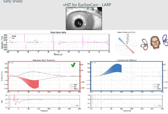
Figure 11 - Vertical impulses test screen
EyeSeeSix
The EyeSeeSix plot can be selected from the left side panel in the summary screen.
![Results for left posterior, left lateral, left anterior, right anterior, right lateral, and right posterior.]](/images/guides/balance/visualeyes/eyeseecam/Figure-12-EyeSeeSix-summary-report.jpg)
Figure 12 - EyeSeeSix summary report
If you have recorded more than one attempt at a protocol, you can choose which tracing you want to use in the EyeSeeSix plot using the drop-down menu for test selection.
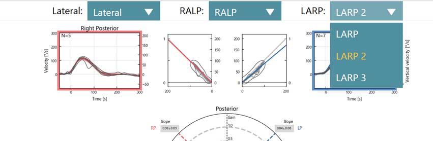
Figure 13 - Drop down menu for multiple subtests
Editing
You can use the left panel option to edit your test results. Use Select Traces for deleting outliers. Remember if you hold the CTRL key down on the keyboard, you can select multiple waveforms. The waves you have selected will be bold so you can see them easily. You can delete the tracings that you do not want to include in your analysis. You can also edit your saccades using the Edit Saccade button. All the numerical data will be shown in the Numerical Results table.

Figure 14 - Edit saccade functions
If you want to look at the tracings with a greater time window than 300 ms, you can change that in the settings menu under computer screen and use the slider bar to adjust the duration. Select the test name EyeSeeCam vHIT (not a subtest) and then the gear in the upper right-hand corner.
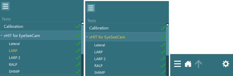
Figure 15 - Steps to make a temporary protocol change
In the settings menu, you can change the Impulse end time in the Computer Screen options.
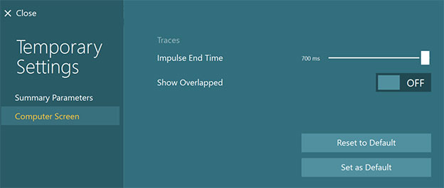
Figure 16 - How to extend the test time display
Ocular motor testing with ESC goggle
If you choose to perform any ocular motor testing while still wearing the ESC goggle, you will need to change the stimuli source back to the TV. Once you do this, you will be asked to recalibrate since the source has changed.

Figure 17 - Recalibration prompt after changing to a new camera source

Figure 18 - Calibration needed for new camera source
Remember the ESC goggle only supports a single camera, so only one eye is recorded when performing ocular motor tests with this goggle. If you notice or suspect any deconjugate eye movements or central pathologies, you should switch to your binocular VNG goggle.
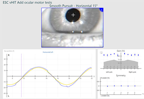
Figure 19 - Smooth Pursuit test completed on left eye with EyeSeeCam camera
For further assistance, if needed, please refer to the Instructions for use and Additional Information manuals. We also have several courses on the Interacoustics Academy website if you need a refresher on how to perform the head impulses or how to interpret the results.
Presenter
