Electrical Auditory Brainstem Response (eABR)
What is an electrical auditory brainstem response (eABR)?
An electrical auditory brainstem response (eABR) is a measurement of the ABR using an electrical stimulus. Instead of a traditional acoustic stimulus the cochlear implant (CI) or auditory brainstem implant (ABI) provides the stimulus that evokes the ABR.
Why perform eABR testing?
eABR testing may be performed for the following reasons:
- To verify adequate placement of the cochlear implant or auditory brainstem implant electrodes during surgery
- To estimate thresholds and comfortable levels in infants, young children or other patients who cannot be assessed using behavioral techniques
- To assist in mapping the cochlear implant or auditory brainstem implant device
- To assess interactions between electrode channels
- To determine the most appropriate rates of stimulation
How to perform eABR testing
Patient preparation
Optimally, the patient should be lying down, asleep and in a quiet environment. Minimally, the patient should be relaxed with their eyes closed during testing. It is important to note that the eABR is not affected by anesthesia.
Electrode placement
Standard ABR surface electrodes are usually sufficient for acquiring eABR recordings. A 3 electrode montage (shown below) is the preferred method while recording from the contralateral side to minimize the high electrical artifact from the Cochlear stimulation, though it is present at both at the ipsi and contralateral side.
Clean and prepare the electrode sites in order to reduce the impedance. Impedance values at or below 3kΩ will produce cleaner recordings. Arrange electrode cables away from the cochlear implant connections to minimize interference.

The eABR response is recorded from the contralateral mastoid, due to the excessive CI radiation/artefacts. For testing ABI patients during surgery a midline electrode montage is recommended (Cz – Nape, C7 for Ground/Common).
Alternative electrode placement:
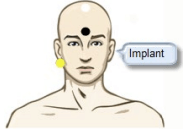
Electrode montage for testing left implanted ear, vertex at position CZ.
Setting up the Eclipse
To conduct an eABR the following is required:
- CI – patient
- CI – stimuli system
- Enable the ‘trigger out’ function in the CI-system
- eABR recording system (Eclipse-hardware and software)
- Trigger cable to connect the CI-stimuli system and eABR recording system
The Eclipse connects to the Cochlear Implant Stimulator which connects to the Cochlear or Auditory Brainstem Implant.

Trigger cable
Connection to the Eclipse is via a standard 6.3mm stereo Jack. The “Trigger In” signal is on the tip of the jack.
The “Trigger Out” signal is a stereo jack with the signal present on the “middle ring”. Ensure that the trigger cable used is a stereo jack. A mono jack will not work.

Trigger cable for Cochlear®
The following two cables sold by Interacoustics are compatible for use with Cochlear implant devices. The cables are available in either 1.5m (Part #: 8004222) or 5m (Part #: 8004236).
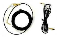
An eABR trigger kit can also be ordered number 8105928. This includes the below two cables and the EPA3 cable collector.
8105924 cable for AB/MedEl/Neurolec/Oticon Medical
8004222 cable for Cochlear Nucleus
Trigger cable connection
- Connect the Trigger Cable to the Trigger port on the back of the Eclipse

- Connect the other end of the Trigger Cable to the Cochlear Implant Stimulator.
Protocol settings
The Eclipse comes with a pre-programmed eABR protocol which can be used immediately or modified to suit the test environment/patient. Refer to the manual for instructions about creating a new protocol or modifying the existing protocol.
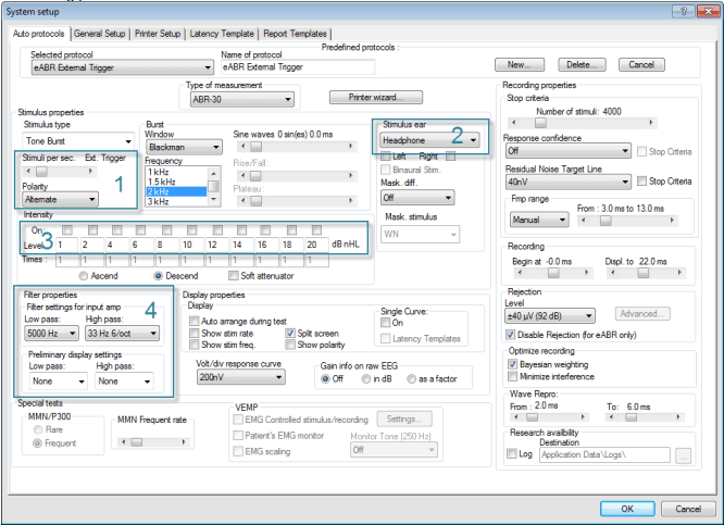
- Ensure the Stimuli per sec. is set to Ext. Trigger.
- Ensure that the transducer selected is Headphone (Selection of inserts would incorrectly subtract 0.9ms from the recording). The actual transducer is the Cochlear Implant.
- The Level values are used to indicate the electrode numbers from the implant for testing - not the stimulus levels to be delivered. Modify as required.
- The Filter settings for input amp. are typically set at 33-5000Hz. For infant eABR, you may like to change the filter settings to 30–1500Hz. Note Filter settings can be changed digitally during or after testing to obtain smoother waveforms.
Recommended test parameters
Settings for eABR acquisition may vary according to the specifications from the Implant manufacturer
- Rejection: If creating your own protocol, be sure to check the Disable rejection (for eABR only) in the Auto protocol tab.
- Stimulus: Set as specified by the CI manufacturer instructions on the CI system.
- Polarity: Set as specified by the CI manufacturer instruction on the CI system.
- Transducers: CI computer.
- Intensity: Set as specified by the CI manufacturer instructions on the CI system.
- Filters:
- 50- 5000 Hz.
- 30-1500 Hz for an infant eABR.
- 100-3000 for adult eABR.
Trigger settings
The trigger signal to synchronize the Eclipse EPx5 and the Cochlear Implant Stimulator may work in one of two ways:
- A signal is sent from the EPx5 software on the Eclipse to the Cochlear Implant Stimulator.
- A signal is sent from the Cochlear Implant Stimulator to the Eclipse hardware (most common setup)
Sending the trigger (synchronization) signal from EPx5
Fom the EPx5 General Setup you must select the type of trigger signal your Cochlear Implant Stimulator device needs (Source or Sink). The trigger signal is a 5 Volt square wave standard trigger signal which is either positive (Source) or negative (Sink). The duration of the trigger signal can be set to meet the needs of the Cochlear Implant Stimulator device. You may find such specifications by referring to the technical specifications supplied by the manufacturer of the device or simply by trial and error.
The onset of the trigger signal starts at 0ms on the recording scale, however the duration of the trigger signal can be changed to work in accordance with manufacturer specifications.

Cochlear Implant Stimulator sends the trigger signal
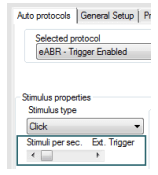
From the Auto Protocols tab, the eABR protocol setting for Stimuli per sec. must be set to Ext. Trigger (move the slider to the far right) in order to enable the External Trigger. This allows the EPx5 to record a measurement every time a 5 Volt Source signal (duration >10µs) is sent from the Cochlear Implant Stimulator. The stimulus rate from the Cochlear Implant Stimulator or other external device must not exceed 50 per second in order to allow sufficient recording and processing time.
Ensure that the trigger signal is actually being sent from the Cochlear Implant Stimulator to the EPx5 software. It may need to be manually enabled in the software provided by the manufacturer of the CI or ABI.
Implant manufacturer software settings
The follow settings are defined in the Implant manufacturer’s software, eABR testing:
- Stimulus type and band number.
- Stimulus rate – Max 20/sec, 10/sec preferred to allow sufficient recording and processing time.
- Stimulus polarity
- Stimulus intensity
- Trigger signal – 5 V TTL, with a duration of > 10µs required for the Eclipse to record a measurement
eABR test procedure
Patient safety
The patient undergoing eABR testing is electrically connected to the Eclipse by skin surface electrodes (the same as when a standard ABR test is conducted). To ensure patient safety is maintained during testing, please refer to the Eclipse safety precautions in the ‘Instructions for Use’ guide.
The patient is not electrically connected to the cochlear/auditory brainstem implant system as it transfers the stimuli using wireless RF (radio frequency) communication. Please consult with the implant device operational manual for appropriate stimuli levels
- Ensure there is a connection between the Eclipse and the Cochlear Implant System via the trigger cable.
- Ensure that the Cochlear Implant System is connected to the patient’s implant.
- Start up both the Eclipse EPx5 software and the software provided by the Implant manufacturer (e.g. Custom Sound by Cochlear®).
- Ensure that the patient is connected as described in the electrode montage.
- Select the protocol (eABR – Trigger Enabled) from the dropdown menu on the test screen.

- Select the test ear and the electrode number for testing from the Man. Stim window.
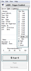
- Press the Start button or F2. EPx5 will wait for the implant software to send the trigger signal before recording begins. If this is the first time performing an eABR, it may be ideal to do a trial test to ensure the two systems are communicating with each other as expected before connecting a patient.
- Follow the instructions provided by the Implant manufacturer to start sending the trigger signal to the Eclipse.
- Collect an adequate number of sweeps to see a clearly defined waveform.
Marking the waveform peaks
- Mark the waveform peaks from the Rec or Edit tab. Only completed waveforms can be marked
- The waveform must be selected (double click on the waveform handle) prior to placing waveform markers
Waveforms can be marked in three different ways:
- Click on the marker button (e.g. I, II, III, IV, V) and then click on the curve where you want to place the marker
- Press the marker number (e.g. 1, 2, 3, 4, 5) on the keyboard. Then use the arrow keys, Ctrl + arrow keys or the mouse to move the cursor to the desired position. Press the enter button or left click with the mouse to place the marker. Using the Ctrl + arrow keys will move the cursor from peak to peak
- Right click on the waveform to select and place markers
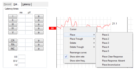
The corresponding ms and μV values will be displayed in the boxes next to the Waveform Markers. Interlatency values will also be calculated after the relevant markers have been placed.
The eABR response is well documented and is said to be represented by two distinct peaks III occurring at approximately 2ms and V occurring at approximately 4ms.
eABR results
Analysis of eABR waveforms and placement of waveform markers should be conducted by a suitably qualified audiologist or other medical professional trained in cochlear or auditory brainstem implant eABR techniques. The following displays some of the common responses seen when recording an eABR.
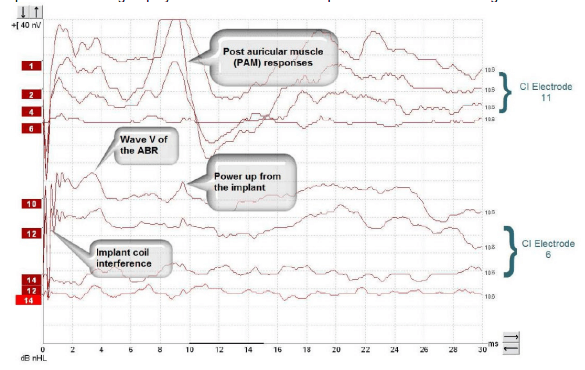
The top 4 curves are the recordings from the CI electrode number 11 starting from a high/comfortable loudness level and decreasing until not heard. Note the PAM responses around 8–10ms. The PAM muscle should not be confused with the earlier ABR wave V responses.
The bottom 4 curves are recoding from the CI electrode number 6 starting from a comfortable loudness level and decreasing. The sharp peaks around 9.5ms are the power up from the cochlear implant. Power up may be so small that it is not recorded.
Note: Interference displayed before 2ms is generated by the implant.
A facial nerve response may also be present around 7.5ms to 11msas a reaction to high level stimulation (Cushing et al, 2006). This example shows the wave V of the eABR and power up from the cochlear implant, which is typically around 10ms in latency. This example shows the wave V of the eABR at shorter latencies (around 4ms), a PAM response and power up from the cochlear implant. All recordings were performed on electrode 11. The curve at the bottom of the display was one recorded with no stimulus to the implant.
Intensity selections made in the EPx5 will not match the intensities delivered by the CI stimulating device. Therefore, keep a record of which recording corresponds to which stimulation situation. The Comments field in the upper right hand corner of the Edit tab can be used to write the actual CI current stimulation level and place for each waveform recorded, as one new comment is available for each highlighted waveform.

Other eABR examples
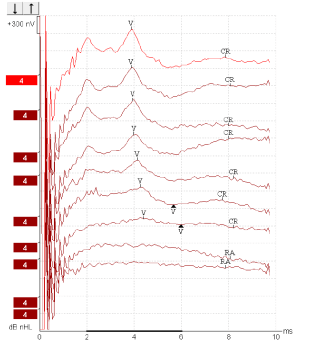
eABR recordings from a Cochlear Freedom adult patient CI – electrode 11, starting from a high/comfortable level and decreasing current to not heard/Wave V is not visible
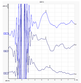
eABR recordings from Advanced Bionics young male patient
Quick tips and precautions
eABR morphology
The morphology of the eABR may be affected by a number of Cochlear Implant factors such as.
- Stimulus polarity
- Frequency band
- Rate and level
- Filter Settings
- RF contamination
- Muscle artifact
- Neural survival
eABR response
- Wave I and often wave II will not be observed due to the RF contamination, and/or stimuli artifact from the implant
- Latencies for eABRs are shorter than traditional ABRs because the electrical stimulus directly activates the neural pathway. Therefore it is recommended to avoid the effects of the time delay associated with the acoustic travel time from the earphone to the neural pathways of the inner ear. The wave V latency is approx. 1.5-2ms shorter for eABRs at high stimulus levels
- It is rare to see Wave VI and VII
- No propagation or synaptic delay, no shift of waveform latency with intensity
- Increased synchrony
- eABR amplitudes are much bigger than standard ABR amplitudes
- Be aware of muscle artifact, typically recorded as a large biphasic potential with a latency of 5-10ms. Muscle artifact typically arises from the facial nerve. Muscle artifact – e.g. PAM (post auricular muscle) are typically seen at a latency of 10ms
Triggering and system optimization
- Consult with the CI manufacturer’s recommendations if special triggering is required
- The EP25 trigger parameters can be set in the General Setup where you select the type of trigger signal your Cochlear Implant Stimulator device requires
- In the Auto Protocol Setup you can select External Trigger in the Stimuli per Second box. In this case the CI system is sending the trigger to the Eclipse
- The trigger signal to the Eclipse must be based on 5V TLL pulses with duration of minimum 10µs
- Braid the electrode lead wires to minimize loop area
- It is important to obtain similar impedances in each measuring electrode as this improves the preamplifier ability to reduce the CI electrical noise
- Use the shortest electrode lead wires possible
Electrical stimulus
- A cochlear implant does not stimulate all electrodes at the same time. The stimulation is serial so a single electrode is stimulated per time
- The electrode wire containing the different stimuli bands/electrodes (e.g. 24) is placed inside the cochlea (Scala Tympani) along the basilar membrane
- When possible do not use longer (wider) pulse widths, since recorded stimulus artifact contaminates a longer segment of the recorded waveform
- Use alternating polarity
Please refer to the Additional Information manual for a description of how to setup the trigger to the Eclipse.
References
Cushling, S. L., Papsin B, C., Gordon, K.A. (2006) Incidence and characteristics of facial nerve stimulation in children with cochlear implants. 116(19) 1787-91
